- Email: info@safeinvert.com
- Tel: +86-18969758632
- Language:


SJR3 Series
Professional soft starter and frequency inverter supplier and manufacturer in China
-
Products Category
-
Related Products
Product Description
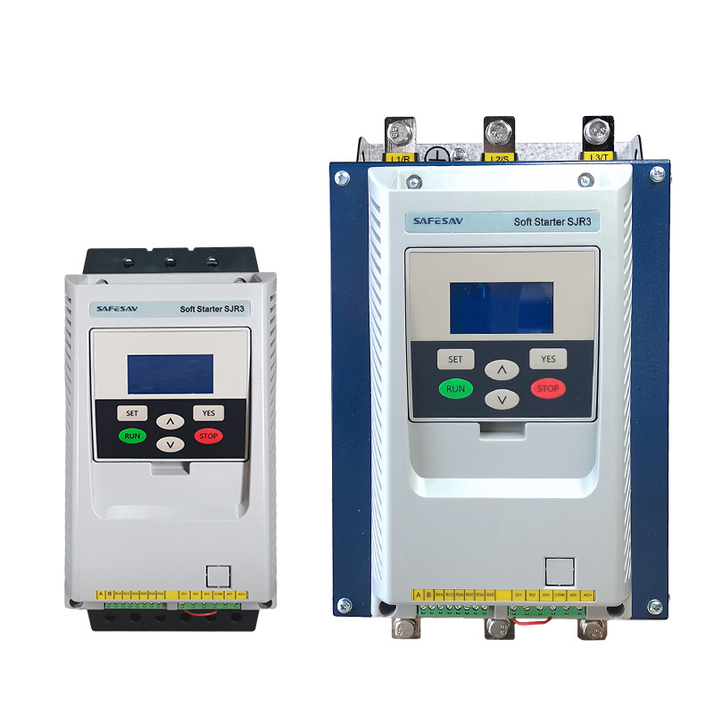
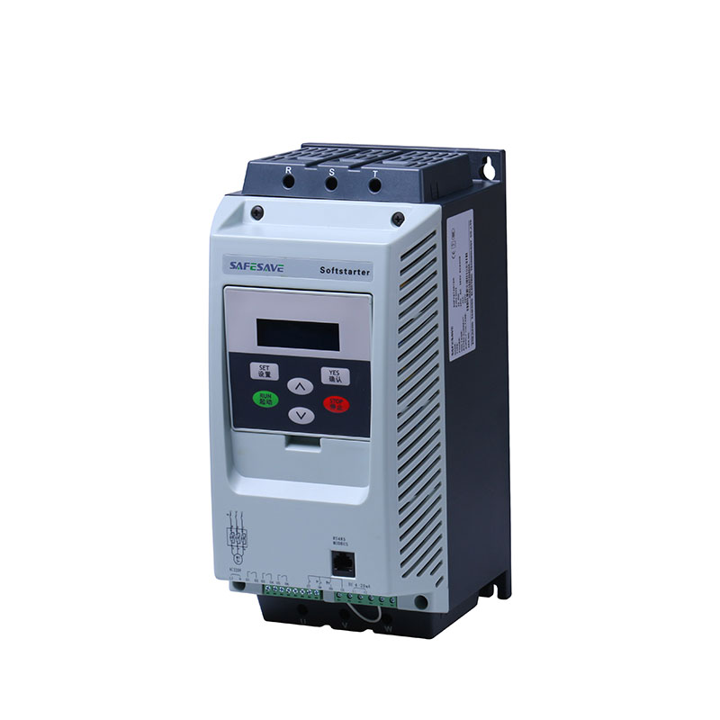
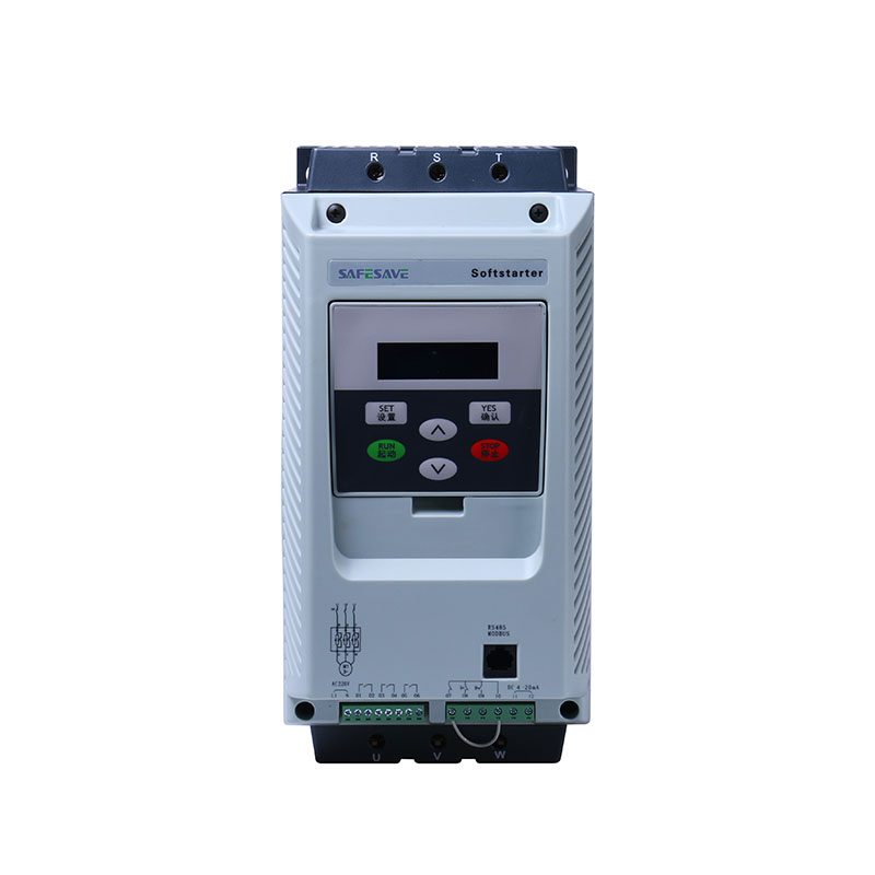
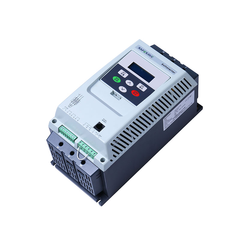
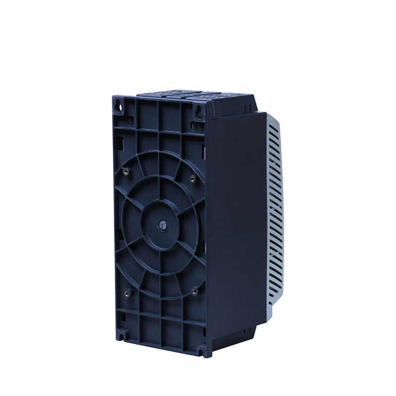
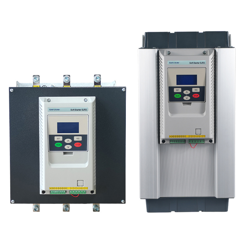
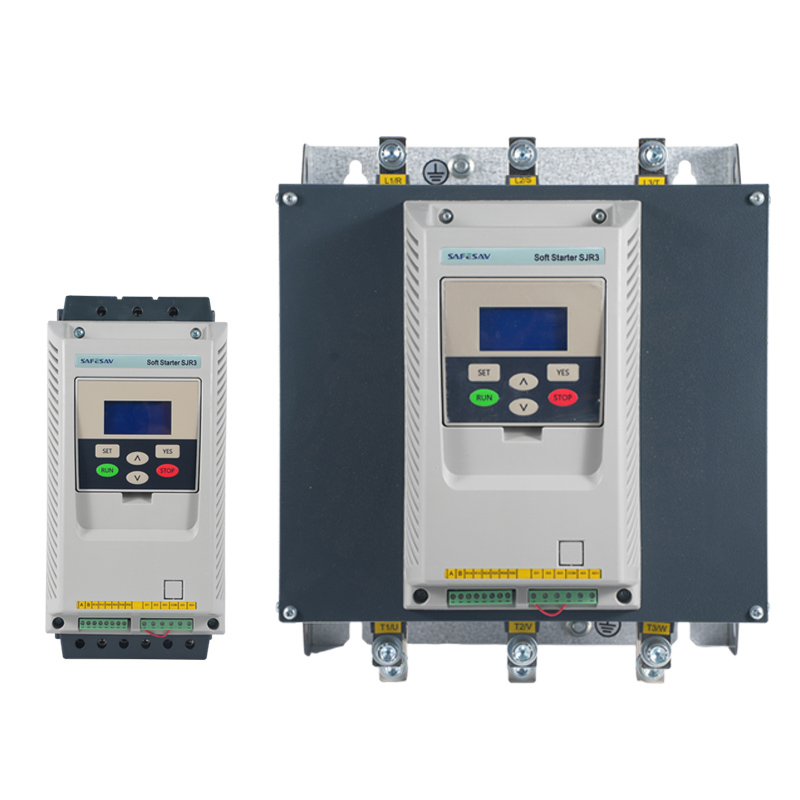
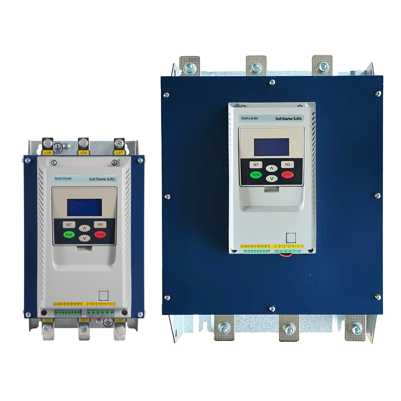
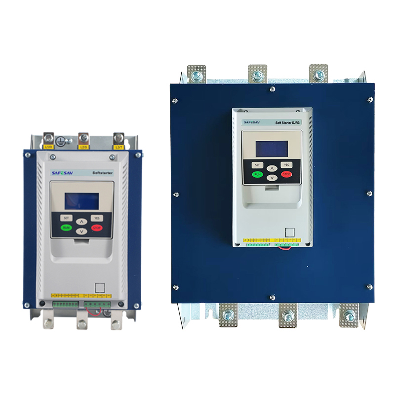
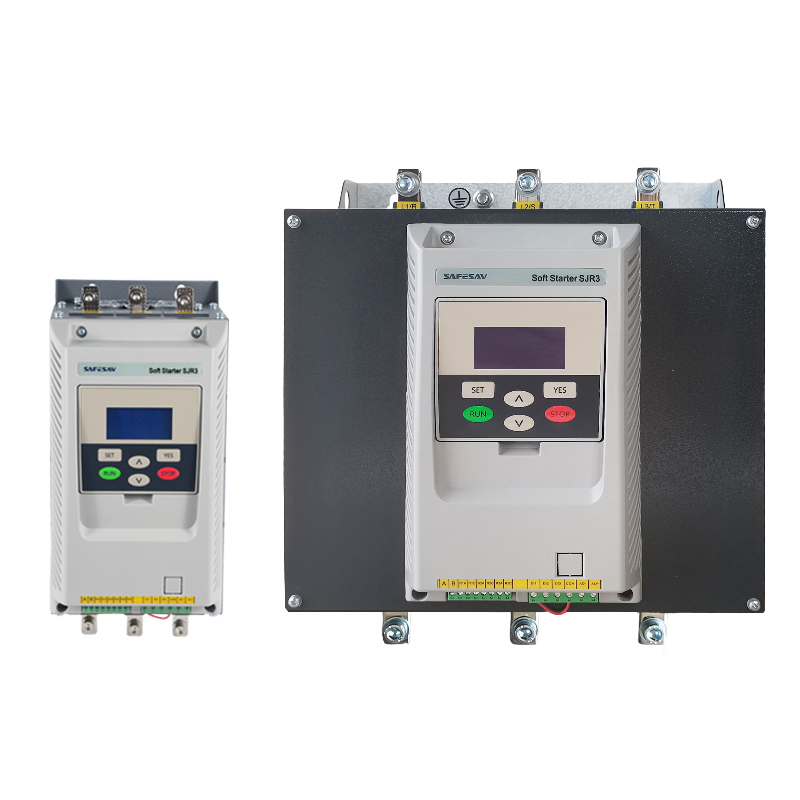
The L series soft starter is a soft starter developed by our company based on the latest product architecture platform (development code"Leopard ")that supports multiple bypass types.
Compared with the platform of the previous generation SJR2 series, the "Leopard" architecture has been greatly optimized and improved in software and hardware.
Based on the latest 32-bit ARM architecture main control chip, the algorithm performance and functions are further improved.
The high-frequency optocoupler-triggered thyristor design replaces the traditional analog pulse drive which effectively improves the internal conduction efficiency of the thyristor and reduces loss. The built-in power supply design enables the product to adapt to wide voltage fluctuations.
The product also has linear temperature detection adjustable three-phase unbalance tolerance and overload tolerance design, so that it can better adapt to the harsh production environment.
Technical Reference
| Standards compliant | GB/T 14048.6-2016/IEC 60947-4-2:2011 |
| Three phase power | (AC) 380V±15%/220V±15%/660V±15% |
| Frequency | 50Hz/60Hz |
| Applicable motors | Squirrel cage three-phase asynchronous motor |
| Start frequency | Depending on the load, no more than 20 times per hour are recommended |
| Impact resistance | 15gms |
| Seismic ability | The vibration force is below 0.5G with the altitude below 3000m. |
| Ambient temperature | No derating is needed with the operating temperature between -10and +40Between+40℃~+60℃,for every 1°C increase,the current decreases by 1.2%) |
| Storage temperature | -25℃~+70℃ |
| Environment humidity | 95% No condensation or water droplets |
| Maximum working height | No derating within1000 meters (above 1000 meters, the current is reduced by 0.5% for every additional 100 meters) |
| Relative to vertical | The maximum working angle of the installation location is not required |
Model Interpretation


Protection and Operation Functions
● Soft start overheat protection
● Input phase loss protection
● Output phase loss protection Three-phase unbalance protection
● Starting overcurrent protection Run overload protection
● Low Power supply voltage protection Power over voltage protection
● Underload protection (anti-dry burning)
● Current limit mode start
● Voltage ramp start
● Soft stop
● Coast to stop
● Programmable relay output
● Fault relay output
● 4~20mA DC analog output
● RS485 communication I/O
● User password and run lock
Product Model
|
Motor rated power(kw)+10% to -15% |
Max. allowable current |
Soft starter rated current |
Soft starter model |
|
| 220V | 400V |
Class 10 application(A) |
ICL rated current(A) | |
| 4 | 7.5 | 17 | 15 | L(1*)-7R5 |
| 5.5 | 11 | 22 | 21 | L(1*)-011 |
| 7.5 | 15 | 32 | 29 | L(1*)-015 |
| 9 | 18.5 | 38 | 35 | L(1*)-018 |
| 11 | 22 | 47 | 42 | L(1*)-022 |
| 15 | 30 | 62 | 57 | L(1*)-030 |
| 18.5 | 37 | 75 | 69 | L(1*)-037 |
| 22 | 45 | 88 | 81 | L(1*)-045 |
| 30 | 55 | 110 | 100 | L(1*)-055 |
| 37 | 75 | 140 | 131 | L(1*)-075 |
| 45 | 90 | 170 | 162 | L(1*)-090 |
| 55 | 110 | 210 | 195 | L(1*)-110 |
| 75 | 132 | 250 | 233 | L(1*)-132 |
| 90 | 160 | 320 | 285 | L(1*)-160 |
| 110 | 220 | 410 | 388 | L(1*)-220 |
| 132 | 250 | 480 | 437 | L(1*)-250 |
| 160 | 315 | 590 | 560 | L(1*)-315 |
| — | 355 | 660 | 605 | L(1*)-355 |
| 220 | 400 | 790 | 675 | L(1*)-400 |
| 250 | 500 | 1000 | 855 | L(1*)-500 |
| 355 | 630 | 1200 | 1045 | L(1*)-630 |
1:Based on bypass type, the above table is applicable for model LN, LE, LB and LX, but not for LD. Please refer to the model descriptions for more details.
2:The above values are given when the maximum ambient temperature of 40°C and the operating environment below 1000m above sea level. The design rated derating caused by high temperature and high altitude should be considered when selecting models.
3: The rated current of the adapted motor cannot exceed the maximum allowable current for Class 10 applications.
Heavy Load Applications
|
Motor rated power( kW)+10% to-15% |
Max. allowable current |
Soft starter rated current |
Soft starter model |
|
| 220v | 400v |
Class 20 application (A) |
ICL rated current(A) | |
| 3 | 5.5 | 12 | 15 | L(1*)-7R5 |
| 4 | 7.5 | 17 | 21 | L(1*)-011 |
| 5.5 | 11 | 22 | 29 | L(1*)-015 |
| 7.5 | 15 | 32 | 35 | L(1*)-018 |
| 9 | 18.5 | 38 | 42 | L(1*)-022 |
| 11 | 22 | 47 | 57 | L(1*)-030 |
| 15 | 30 | 62 | 69 | L(1*)-037 |
| 18.5 | 37 | 75 | 81 | L(1*)-045 |
| 22 | 45 | 88 | 100 | L(1*)-055 |
| 30 | 55 | 110 | 131 | L(1*)-075 |
| 37 | 75 | 140 | 162 | L(1*)-090 |
| 45 | 90 | 170 | 195 | L(1*)-110 |
| 55 | 110 | 210 | 233 | L(1*)-132 |
| 75 | 132 | 250 | 285 | L(1*)-160 |
| 90 | 160 | 320 | 388 | L(1*)-220 |
| 110 | 220 | 410 | 437 | L(1*)-250 |
| 132 | 250 | 480 | 560 | L(1*)-315 |
| 160 | 315 | 590 | 605 | L(1*)-355 |
| / | 355 | 660 | 675 | L(1*)-400 |
| 220 | 400 | 790 | 855 | L(1*)-500 |
| 250 | 550 | 1000 | 1045 | L(1*)-630 |
1:Based on bypass type, the above table is applicable for model LN,LE, LB and LX, but not for LD. Please refer to the model descriptions for more details.
2:The above values are reference values given according to the maximum ambient temperature of 40°C and the operating environment below 1000m above sea level. The design rated derating caused by high temperature and high altitude should be considered when selecting models.
3: The rated current of the adapted motor cannot exceed the maximum allowable current for Class 20 applications
Wiring Diagram
Basic wiring diagram
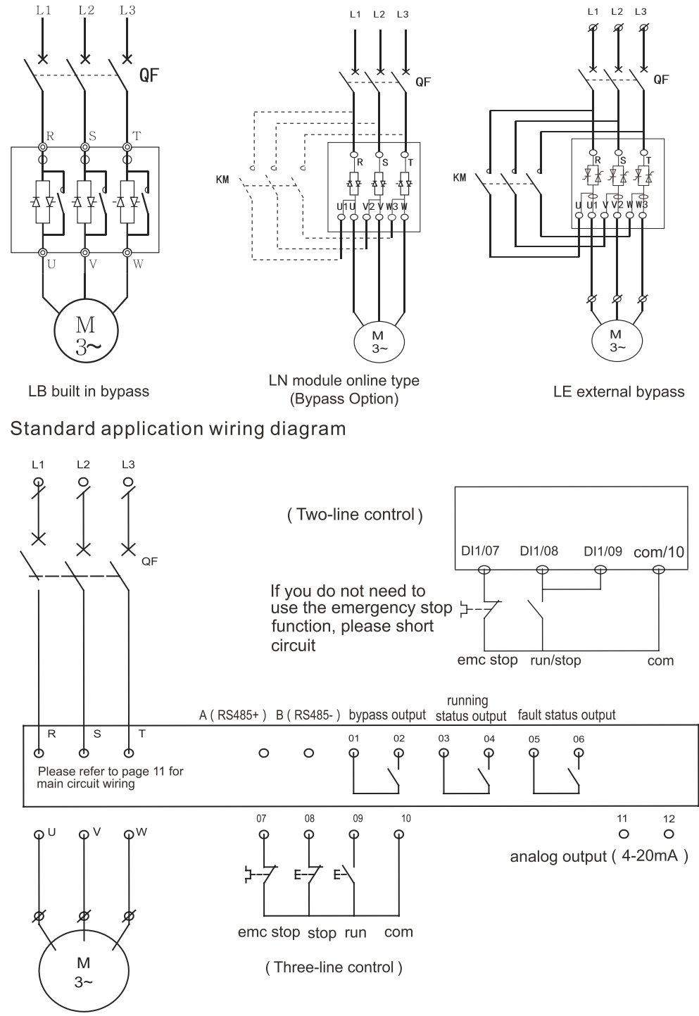
Control Terminal Connection

| NO. | Title | Download Link | |
|---|---|---|---|
| 1. |
SAFESAV SJR3-L Series Soft starter |
Download Link | |
| 2. | Instruction Manual-SJR3-2000 | Download Link |
Welcome to our website. If you have any requests or suggestions,please feel free to email us at info@safeinvert.com or use the following enquiry form. Please allow us to provide you with the best service.

